E Gadgets 5: Compressor for Electric Guitar with PC817
Last Updated on January 2, 2022
First Published on November 12, 2020
Download PDF File: Compressor for Electric Guitar
* (1/2/2022) I updated the file to V.1.5.1:
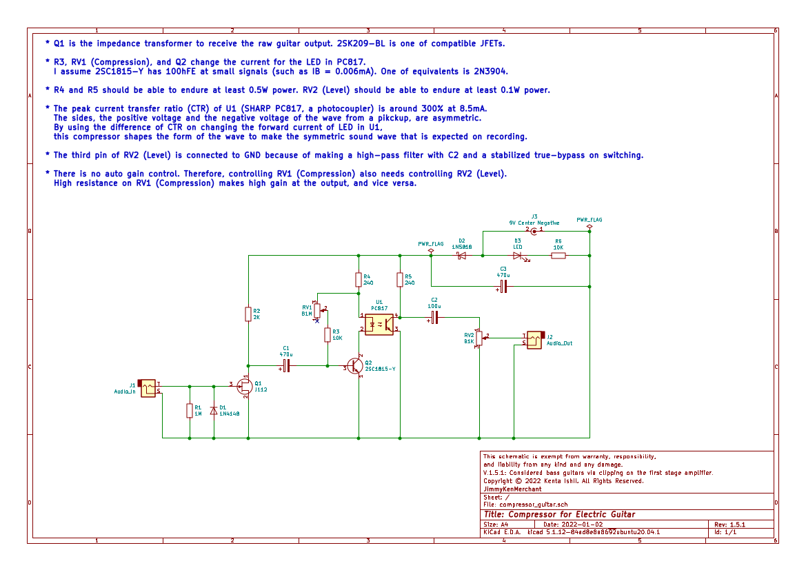
I removed a potentiometer for the threshold (adjusting the input volume), and added a diode for clipping to consider bass guitars. JFET is a diode on the positive voltage of Gate to Source, and the additional diode works on the negative voltage. Unlike a tube, JFET doesn't have a leak from Gate, and no negative biasing with JFET used to be applied on impedance transformers for electret condenser microphones (ECMs) and other small signal receivers.
* (11/25/2020) I updated the file to V.1.4.1:
I added a potentiometer for the threshold (adjusting the input volume). I think numbering legs of a potentiometer should be depending on an assembling basis. I watched several schematics online that the numbering is different from my thought. In guitar works, however, the 3rd pin on the flip side is for grounding. When you solder a potentiometer, you need to consider of the function, i.e., how the potentiometer works on turning clockwise or anti-clockwise regardless of numbering in schematics and boards.
* (11/16/2020) I updated the file to V.1.2.1:
I replaced BF256B with 2SK209-BL. In my experience, BF256B doesn't seem to invert the phase. I confirmed that BF256B is, in fact, a N-channel JFET because of its working as a diode.
The sound of electric guitars, especially with single coil pickups, is brilliant. However, engineers in recording nowadays may dislike the sound because it's a little bit tricky. The wave of the positive voltage and the negative voltage is asymmetric, but engineers expect the symmetric wave like in their text book. Guitarists may need to fit with engineers' demand for money. The reason of humbuckers on so-called "modern" guitars comes from this matter. Humbuckers often sound fatter than single coil pickups, i.e., the sound wave is slightly similar to a sine wave which is symmetrical. Engineers aim to make the track filled by the sound power, and try to fill a track by sound waves which are in view of the peak and the area. The sound power is related to listening. If the sound power is bigger, you feel that the sound is louder. In the music business, loudness is a big keyword to sell tunes. Therefore, engineers use not only peak meters, but also RMS (root mean square) meters and VU (volume unit) meters for monitoring loudness. The sharp attenuation of a sound wave is disliked because it's easy to be clipped in spite of the little area to give the sound power, loudness. Besides, asymmetry causes easy clipping.
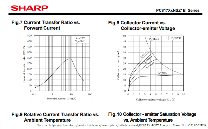
I quoted a part of the datasheet for SHARP PC817 (Download PDF File) because of possible unlinking with the actual PDF file from the company through maintaining its website.
Check out Fig. 7 in the datasheet of SHARP PC817, a photocoupler. The peak current transfer ratio (CTR) of PC817 is around 300% at 8.5mA. By inverting the wave through the first stage with BF256B, PC817 suppress the asymmetric peak at the positive voltage using the CTR curve. Note that PC817 is a well-know chip and several vendors distribute similar models. Chips which have the same peak and the curve of CTR may fit with this circuit. However, several photocouplers, such as PC8171, are classified as low input current, and this type of photocouplers don't fit with this circuit.
* Using Fig. 8, we can determine the resistance of the load (the resistor between VCC and the collector of U1, i.e., R5) and the forward current (IF) of LED. You can draw a triangle which the edges are the left right corner (0 and 0), actual VCC voltage on the VCE axis, and the maximum current (VCC divided by the resistance of the load you consider) on IC axis. The sloped straight line you drew crosses several curved lines which indicate IF. The point of the crossing expects VCE and IC on some IF (watch gauges on axes perpendicularly, i.e., a square in the triangle). This measuring also can be used with regular transistors.
I tested the circuit using Raspberry Pi 3B, UCA222, Les Paul SL, and my DIY preamp. Note that UCA222 records sound with reverse phase. Therefore, I inverted phases of all tracks and normalized to -4dB at peaks. Peaks on actual recording were -12dB to -18dB.
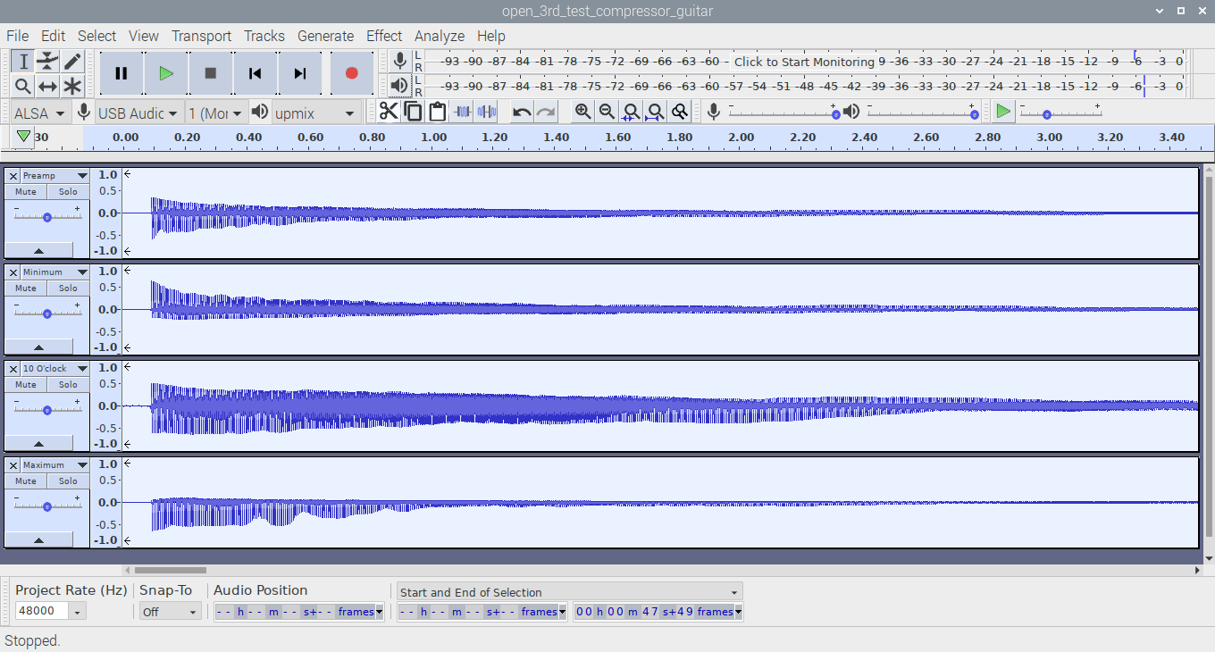

Deep blue indicates the peak, pale blue indicates the RMS.
Here are tracks on plucking the open 3rd string (G3 = 196.00Hz) in four conditions. The first track is recording sound through only my DIY preamp. Other tracks are through the compressor. The second track is with the minimum resistance of the RV1 in the compressor. The third track is with about the 30% (10 o'clock) resistance of the RV1. The lowest track is with the maximum resistance of the RV1. For the sake of high power input, these seem to be clipped, but you can see that the track of 10 o'clock has the most power and the longest sustain.
You can calculate one cycle of the wave for G3 is in 1 / 196 = about 0.0051 milliseconds. However, the waves in tracks doesn't fill out the cycle, and these seems to be just the half of the cycle. This emptiness causes 2nd harmonics. To fatten the sound, we need to fill out the cycle by an equalizer or a low-pass filter. Edges made of compressors may also be shaped by these. Make the peak of your equalizer close to the frequency of the fundamental wave. In this case, it's 196.00Hz.
I studied how pickups work as described below.

In the second and the third tracks, I attached my iron screw driver (1.6mm flat blade) to a pole piece, and released the driver from a pole piece. Note that the first track is the output of a 1.5 volts AA battery with a voltage divider. The voltage at 1.5 volts is so high as an audio signal, and it's DC unlike an audio signal as AC. Make a voltage divider that is made of resistors such as ones having two 10K ohms to output 0.75 volts. Then, output the voltage at 0.75 volts through a capacitor such as one having 100 microfarads.
I checked polarity of pickups in Les Paul SL. Both are the same polarity. In checking with my compass, I found that the neck pickup has the north pole on its upper side, and the bridge pickup has the south pole on its upper side. Polarities of both pickups seem to be the same, and I guess there is the difference on winding each wire. When my screw driver touches a pole piece, the voltage goes to the positive side. However, the polarity goes the opposite side at first because of coil's self-inductance. The coil has the magnetic field by the magnet in advance. The coil flows reversed electric current by counter electromotive force when the magnetic field changes. After the end of the change, at last, the coil starts to flow electric current in the direction that we expect. The 90 degrees phase shift between the voltage and the current of a coil seems to be described by this phenomenon.
The asymmetry comes from the system of pickups. Every pickup, which has a coil and a magnet, picks vibrations of strings as an electric current using electromagnetic induction. If strings are magnetic bodies, the asymmetric current wave doesn't generate. However, typical strings are made of steel and a magnet is set in a pickup, and strings become magnetic bodies as long as these are closer to the magnet. Main theories online tell that Maxwell's corkscrew rule (also known as right hand thumb rule) describes how the coil of a pickup generates electric current. When you move a magnetic body closer to a coil, the coil generates electric current, and when you move a magnetic body further from a coil, the coil also generates electric current. When strings are further from the magnet in these vibrations, strings receive less magnetic flux. Time differential of receiving magnetic flux by strings relates to generate an electric current in a coil.
I think that the waves shown above are made of coil's self-inductance. You can test how plucking manners affect sound waves. In the regular plucking, push the string by your thumb and release it, the wave starts from a positive pulse. Meanwhile, in the plucking manner, pinch the string and release it, the wave starts from a negative pulse. The second manner should have a positive pulse in Maxwell's corkscrew rule because the first movement of the string is closing to a pole piece, but it doesn't occur as long as my preamp has no phase inversion. Through the polarity check above, We have already found that the pickups are regular ones. Touching a pole piece by a screw driver generates the positive voltage. However, the change to the positive voltage is led by the change to the negative voltage because of coil's self-inductance. Unlike the polarity check, besides, the vibration of a string doesn't stop immediately. Check out the polarity check again, the area of positive voltage on leaving is less than the area of touching because of jamming by magnetic field. This is why the asymmetric wave is generated.
By the way, acoustic guitars and drums have 180 degrees inverted phases between these top surface and these bottom surface because the sound wave of these is made of bending of boxes. Both instruments start these sound from beating on the one side of surfaces. If one side becomes deflated, another side is inflated, and vice versa.