HR Noise 9: Drilling Box
Last Updated on January 5, 2022
First Published on July 13, 2020
Let's drill a box for my DIY preamp! Before drilling holes on an aluminum box, check 4 items as below.
1. Wear goggles, long sleeves, and hand gloves to cover your eyes and skin from any accident.
2. Get any cleaner to gather aluminum tips made by your drilling. Caution that aluminum tips can be fired!
3. Secure your working place not to damage any material and yourself. In my opinion, the works is very dangerous. If you want any drilling work as a beginner, you should do it with your lovely family who have already experienced the work.
4. Do it on your own responsibility at all. If you do it alone, I can say you will get any accident. Drilling is the tough work harder than things you think.
* In the machine industry, the automation of drilling started from 1950s in the western world. Accurate drilling by a milling machine gave the industry mass production more than ever, e.g., cars. Milling machines with computers are now working instead of skilled workers. Skilled workers are the supreme people in the diligent industry, and they should be praised in future. However, in the WW II, the accuracy of making weapons in Japanese military was bad because skilled workers were in the battle field as soldiers who were also patriots with strong muscle. Its low operational capacity causes losing in battles. In contrast, the U.S. had already made the method to make weapons in mass production with non-skilled workers. In Japan, almost milling machines are made in Aichi, placing Toyota's headquarter. Okuma & Howa, Toyota's sibling company had made working machines including milling machines. The company has been merged to Okuma. Note that Howa Machinery, the big brother of Okuma & Howa and rifle manufacture, holds commercial rights to sell the machines. There is a little part of the Aichi's industrial syndicate in this story. Oda Nobunaga, one of the big three in Sengoku period, who dominated Aichi region introduced rifles to the Japanese battle field from Europe. He is also known that he liberated commercial activities through abolishing cartels in his dominance. His commercial policy was like the U.S. nowadays.
-------------------------------------------------
Day 1:
I printed my drilling plot for my DIY preamp (preamp_enclosure.dxf) with actual sizing. I used a plain A4 paper for printing. Not to use masking tapes afterwards, a A4/Letter sticker paper may be good. Note that in my experience, Windows version of LibreCAD (V.2.1.3) can't use the function of Construction Layer, otherwise the software freezes. If you want make "Draft" layer visible in the Windows LibreCAD, uncheck "Construction Layer" in "Layer Settings" menu which is popped up through right clicking "Draft" in "Layer List" then left clicking "Edit Layer Attributes".
* (7/18/2020) I updated the file to V.1.2.2:
Removed a duplicated "Height of Locking Part of Lid" text box.
Swapped "JACK-IN" and "JACK-OUT"
* The dxf file doesn't log the history of changing. The file is human-readable, so it can be logged using Git.
Open the file with LibreCad > Make "Parts" and "Parts Dimension" invisible in layer List. > File > Print Preview > Select "1:1" on a pull-down menu at the left of the "fixed" checkbox in the "Tool Options" toolbar. > Press and hold "CTRL" and "P" on your keyboard.
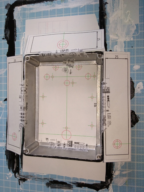
Cut the printed sheet to fit with the inside of the bottom and out of sides to be drilled. The bottom sheet is cut along with the black lines, and the side sheets are cut with the gray lines. Paste cut sheets to the box by masking tapes. Make sure that the bottom sheet can be pasted on the center of the box, and the side sheets can be aligned at the top edges. Check and arrange coordinates of holes in the side sheets with watching green lines of the bottom sheet. Caution that sheets describe inside of the box. Sheets for the left and right sides are alternated because of pasting these outside of the box. The sheet for the upper side has symmetrical, so it can be just pasted outside. Dimensions of these sheets are exactly the same as each other.
* (Updated on 1/5/2022) I uploaded a fixed plot (V.2.1.1) for the issue as I described above. The view becomes just outside of the box, i.e., an exterior elevation without a lid.
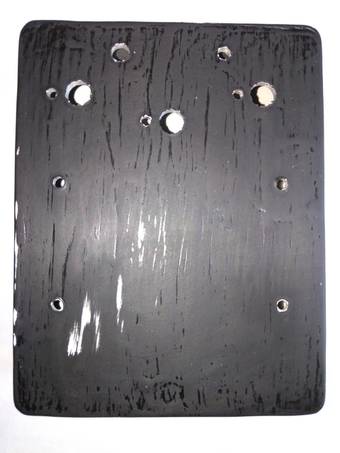
To mark centers of drilling holes, I used handy pin vises, 1-3 mm. Drilling holes are indicated by red circles and centers of these are indicated by green crosses. Use 1 mm one at first, then gradually expand sizes. Don't try to make holes by these tools. The purpose of using mini drills is just only mark centers, otherwise the drills are broken. I peeled off the sheets after marking centers not to stick glues of masking tapes to the surface and the inside of the box. In this case, I don't apply a foot switch, so I didn't drill holes for the switch.
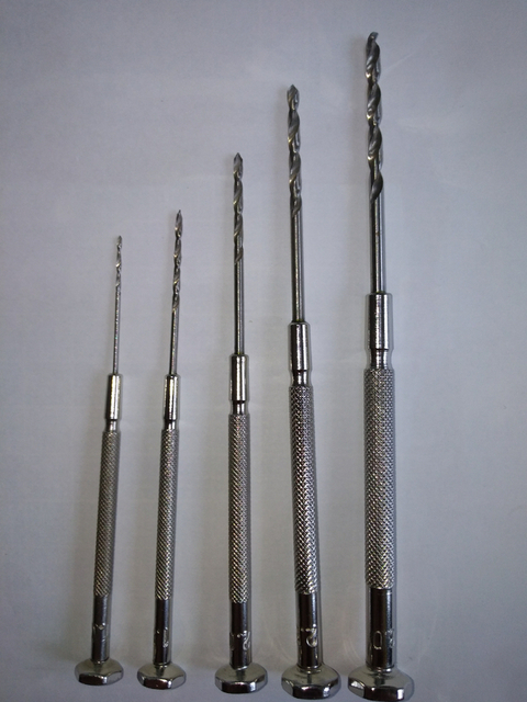
Then drill holes by 2.5 mm and 3.5 mm drill bits for metal, applying gradual expansion as well as pin vises. I used a hand drill which can attach a drill bit up to 8mm. To fix the box with a tooling table, I used a 100 mm wide cramp and wood boards. However, the method can't fix the box on drilling with a 3.5 mm bit. More cramps and an intermediate 3 mm bit may be needed. You're better off using a drill vice for fixing. The photo as below is just showing tools I used. Fixing idea should be thought by yourself for safe drilling.

Drill holes 3.5 mm diameter, except holes 3mm diameter for locking potentiometer. Holes for M3 screws, to place an electric circuit board, are plotted as 3.2 mm diameter, however I expanded these up to 3.5 mm diameter for adjustment on placing. Repair damaged coating on drilling. If you have already waxed the coating, remove wax around the point to repair by sanding, etc. Otherwise, the wax repels the paint.
-------------------------------------------------
Day 2:
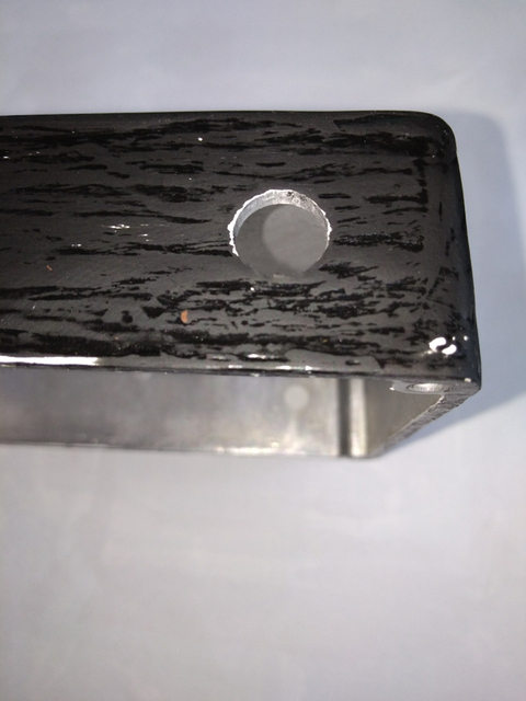
To expand holes to fit with my plot, I used a taper reamer for holes 3-12 mm diameter. I checked the size of holes with actual parts I will apply. The cast aluminum box doesn't make conspicuous burrs on drilling holes.
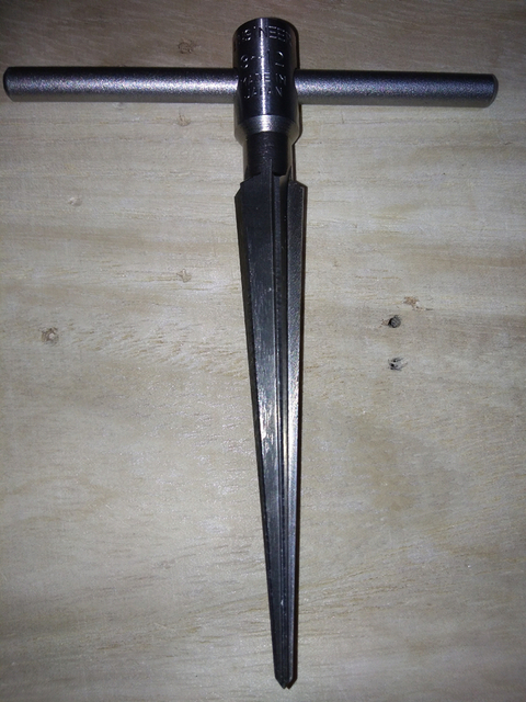
Sand box by a #1000 water proof paper. The box in photos is dried after sanding.
-------------------------------------------------
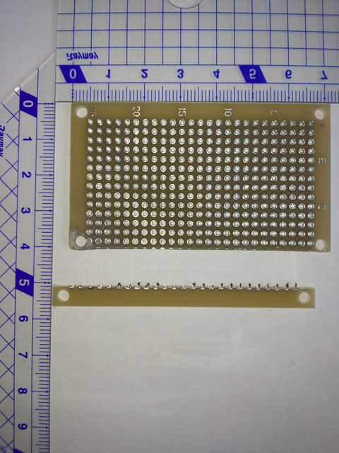
In my plot, the dimension of electric circuit board is 72 mm * 42 mm. It's because of POT2. If plotting to place only two POTs, the well-known size of universal boards, 70 mm * 50 mm bakelite can be applied. Anyway, I have the one with 72 mm * 47 mm glass fiber - epoxy resin. I cut the board using an array of holes.
Not to get an accident, wear goggles, long sleeves, and hand gloves to cover your eyes and skin from any accident. This work is dangerous as well as drilling.
1. Make a line by a craft knife on an array of holes, from an edge to another edge of the board. The line should be made on both sides, the front and back. Use a ruler to guide the knife. The notch of the line should be deep as long as possible.
2. Snap the board along with the notch of the line. I used two wood boards to make a step to fix by hand. Not to scatter small tips, cover the board by rags, etc.
3. Make holes at lower corners by hand pin vises. Use the bottom sheet used in drilling to check coordinates of holes. Sand sides, especially the snapped side, by a small file. The lower left corner is broken on snapping, so I repaired the corner by epoxy putty before sanding.