HR Noise 11: Assembled DIY Preamp with LM386
Last Updated on September 7, 2020
First Published on August 1, 2020
Let's assemble my DIY Preamp!
I tested schematics on Bread Board of Impedance Transformer and Preamp.
This preamp is the combination of an impedance transformer and an amplifier. There are two core concepts.
1. An impedance transformation/conversion should be done close to the guitar as possible to reduce noise, e.g., hum. Cables with high impedance pick up external noises. This concept is come from my ukulele DIY pickup. You can imagine pickup's equivalent circuit that consists an AC generator, a coil, and a resistor in series; and a capacitor in parallel. The circuit makes the various impedance with frequencies. A high frequency makes higher impedance than a low frequency in this circuit. The different characters among pickups are caused from the differences of equivalent circuits. The impedance transformer/converter (Q1) and the 1M ohms resistor (R1) flatten the impedance on each frequency on your guitar. Whereas other preamps/buffers convert the impedance after cabling. Long cabling adds a coil, a resistor, and a capacitor to the equivalent circuit, affecting original characters of pickups.
2. To improve signal to noise ratio (S/N), output impedance should be low as possible. High impedance output also picks noises and feedbacks to the input, looping amplification of noise. So, this preamp plotted to be used with low value in the level volume.
Basically, this preamp is not aiming overdriving (high gain) and distorting (high level). However, I considered of absolute ratings to fit with these usages.
I know products of noise gates are on digital these days. However, I hope that you recognize these analog concepts also gives you brilliant clean sound. This preamp is set at the first stage of pedals, so you can logically apply a noise gate afterwards. I haven't tested other pedals with this though. I've tested this with UGREEN USB audio interface so far.
Note that in the schematic, C1 and RV1 make high-pass filter, but this filter is also affected by 50K ohms input impedance of LM386. For example, on the full volume, the high-pass filter is made by 1u farads and 33K ohms (cut-off = 4.82 Hz), whereas on the no volume, the high-pass filter is made by 1u farads and 100K ohms (cut-off = 1.59 Hz).
Download SVG File: Board Layout (Actual Work)
Download SVG File: Board Layout (Modified Afterwards)
Board layouts are considered of heat treatment through widening the grounding pattern.
Painting Aluminum Box (HR Noise 8)
Drilling Aluminum Box (HR Noise 9)
Plottting Board Layout by KiCad (HR Noise 10)
Note that series of HR (Home Recording) Noise is mainly the story to make this DIY preamp.
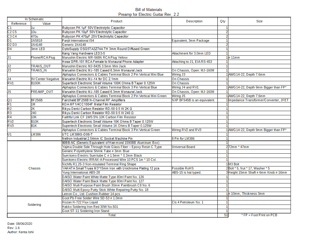
BOM omitted prices as below. I calculated the total price is at approx. 6000 yens at this time. I bought these parts in electronic shops sited Akihabara and Amazon Japan, 100 yen shops, etc. I bought almost all online except goods in 100 yen shops where I mainly bought paints. These are considered of availability to obtain. However, the DC jack (J4) may not be on sale outside Japan. It's smaller than the ordinal triode. I used AWG 24 wires, but terminal blocks accept AWG 14-22 in the datasheet. However, these blocks seem to be accepted AWG 24 wires which are twisted and soldered in my case. Note that the wire I used is strong, but it's difficult to peel the sheath without a wire stripper.
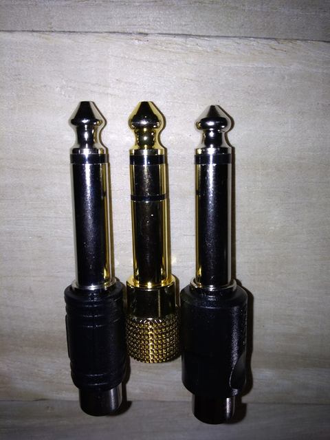
Jacks I applied are manufactured by Marushin Electric, whereas in North America, these are mainly manufactured by Switchcraft. There are differences in sizes. Plus, acceptable plugs may differ even in the same type. For example, a phone jack in Japan is on JIS C 6560 and the jack in North America is on EIA RS-453 / IEC 60603-11. Check out the 3rd party review of diffrence in size (Japanese language). The photo as below shows a RCA adaptor (JIS), a stereo 3.5mm (mini) adaptor (JIS), and a RCA adaptor (EIA/IEC) from left to right. You can see an apparent difference in shapes, tips to moats. Center and right ones can be accepted by the jack of Les Paul SL, but left one can't. Left one produces noises to be caused from its contact failure. I think that Moscow shape would be better than a solid shape.
* Marushin Electric cited on Kawasaki, the centre of manufacturing telecommunication equipment in Keihin industrial zone before the movement to Chinese factories. Since the movement, your clock has ticked over 30 years. You can see the commitment in purchasing products manufactured by neighbors, particularly for cars. The movement apparently ignored of the math to the commitment. I can say I would buy a second/third handed car if I need. Since 80's, the promotion for the industrial sector of southern Kanto plain; Keihin, Syonan, and the bay area in Chiba; equals to be dead because it closes to Tokyo, and the residential sector is stronger than the industrial. This area was historically known as a wilderness until Edo era as opposed to Aichi, Toyota's headquarters in central Japan. The lack of nativeness in Keihin may take presidents moved out factories.
* In Manyosyu (万葉集), an ancient collection of Japanese poetry in the 7-8th century only remains one poetry which shows manufacturing linen in this area. Azabu in Tokyo seems to be named from Japanese word of linen. Population in Kanto at the time was concentrated to northern area because of suitable rice cultivation. Overall, this means the southern area was a wet coastal area where rice was not able to be cultivated. In the world, cultivating a mouth of a big river began since the early modern period, such as Shanghai, Venice, and Edo = Tokyo. The ancient history of mankind is made of the grain producing records for taxation. Nobody in this time can't know the life of people in such a wet land in past days a long time ago.
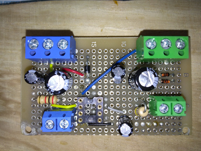
It's the main board I soldered.
Its flip. Hmmm, maximum 4 mm height of surface - solder summit.
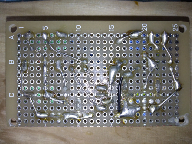
I used a lead free solder (Sn 99%, Ag 0.3%, Cu 0.7%) not only for the board but also potentiometers. I think I would use a lead solder for potentiometers (POTs) because these are heat sensitive. Soldering between the flip of a POT and a pin is able to be made by 30 W soldering iron and a lead free one in this case, however this combination is not recommended. Ideally, you can use at least a 40 W iron and a lead solder not to break a POT. It's the best to use a lead solder for audio parts, e.g., speaker units, etc. because the temperature of an iron is needed lower than a lead free (pads of speaker units for soldering may be made of papers!). Note that I sanded the flip of a POT by #180 before soldering then pre-soldered the flip.
* RoHS directive restricted to use a lead solder for products in Europe because lead is harmful against our body. However, heat break also takes parts become just garbage which is also harmful against our environment.
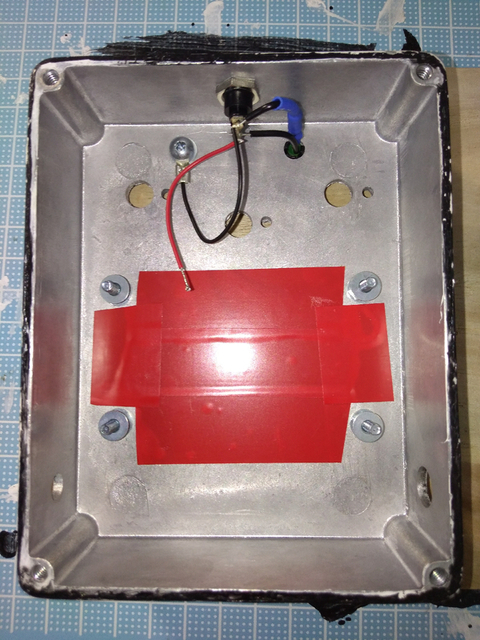
Wiring was more difficult than I thought. You can see curved wires for flexible length to reach out terminal blocks. Straight wires don't give you flexibility on length. I recommend that you solder wires, with curving scenarios, on jacks and POTs before placing these on the box. Wiring of the DC jack is exceptionally soldered because of a LED module which is directly connected. I covered the surface below the board by insulated tapes just in case.
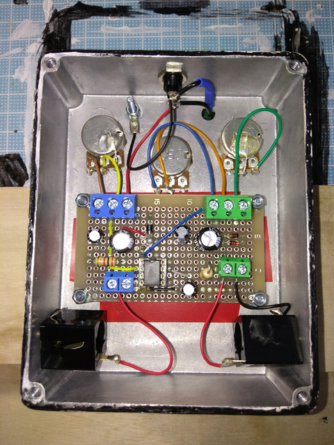
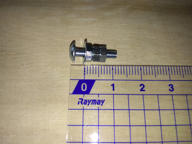
To hide ground loops, I only grounded between the green mini terminal block and the monaural jack by a black wire. The DC jack is insulated to the box, so it's grounded to the box by a terminal ring connected by a M3 bolt, a nut, and a washer (watch out the connection of the black wire between RV1 and RV2). Note that the terminal ring and the wire are soldered in addition to cramping.
Numbers of pins are assigned left to right looking the flip of a POT. This is because of clockwise voluming. Note that RV3 is specially wired at No. 3 pin with a green wire because it's volumed by increasing resistance.
To place the main board, I didn't used a washer between the board and a nut because of a possible short circuit on the prototype. I only used a washer between the box and a nut.
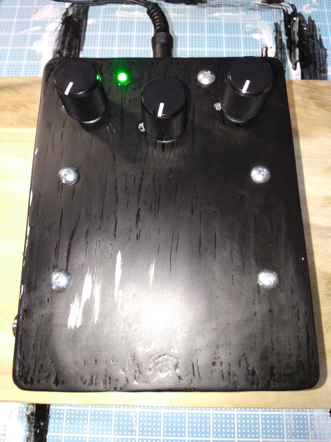
I think this layout is useful because nuts can be fasten using radio pliers after assembly. I put adhesive cushion rubbers to all corners of the lid after putting because the coating of the box I painted is sticky in plain surfaces.
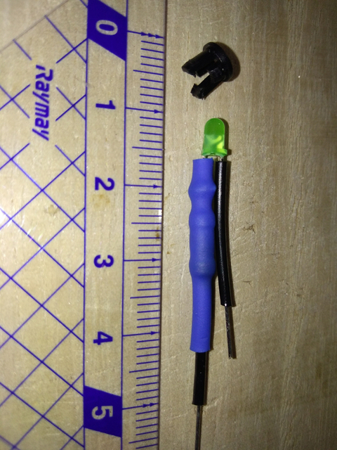
So, I made the LED module like this. Cut a lead on the cathode of LED and a lead on the 10K resistor, then soldered with supporting by clips. I paste liquid solder flux to leads before soldering with a lead free.

I applied two types of shrinking tubes, diameter 3mm (blue) and 1.5mm (black). These also can be layered. The gasket in a photo is placed from the front of the box, and the LED module is mounted to the gasket from the back of the box.
Spacers between the board and the box is made of three nuts and a washer, having approx. 7mm length. I used iron bolts with chrome plating. Note that hexavalent chromium is prohibited to use in product by RoHS (Europe) directive. Make sure to fasten nuts from left to right (the closest nut to bolt's head at first) in the photo below.
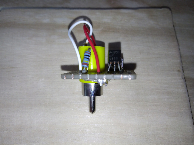
I also made a module on a guitar. These are a self-made board and a Marushin RCA (phono) plug. The board around the approx. 10 mm hole is repaired by epoxy putty and sanded edges for shaping by a mini file. I sanded through-holes before soldering by a #1000 water proof paper to clean surfaces of holes.

To fit this condition, I cut the upper half of the case and the metal for crimping at the negative pole.
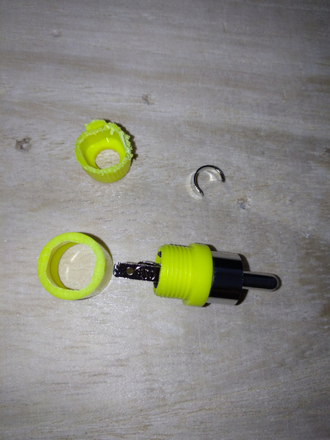

I applied stereo 3.5mm (mini) jacks to connect between Les Paul SL and my DIY preamp because of using an OFC parallel cable which are competitive on value and able to put on ferrite cores. However, the mini jack in my preamp is replaced to a monaural 6.35mm = 1/4" jack because the mini jack can't be fixed without any glue. I've still stayed to use the mini jack in the module, so I need any mini jack to 6.35mm jack adaptor.
So, the next phase on my DIY preamp is to embed this module to my Les Paul SL. This module isn't water proof and has mechanical weakness. You need just a 2M ohms POT and a BF256B to embed, and don't need jacks and plugs.
The sound of the preamp is good without grounding because the aluminum box acts as the ground in terms of aleternating current. Uniqueness in the sound is straightness as if it amplifies unplugged sound of a guitar by a microphone.
Caution that this system is not reliable so far. It's DC biased between the guitar and the preamp. So, in my testing, several issues will occur...