LesPaul SL 7: Go Customize
Last Updated on July 28, 2021
I embedded a module used with my DIY preamp into my Les Paul SL.

The external module is convenient because your guitar is safe from risky customizing, but it's also weak mechanically in several situations such as your premium stage. I think that 3.5mm stereo mini jack/plug is small and may be broken through rough handling.
You wonder why I insist on this preamp. It's because of good signal-to-noise (S/N) ratio, i.e., low noise such as hum and high frequency from electric gadgets. In my experience, this preamp stays -60dB on background noise at a house. In studios and stages in which is electrically grounded well, I expect it would have less background noise than a house.
Download PDF File: Schematic of Preamp
Download PDF File: Plot to Customize Les Paul SL
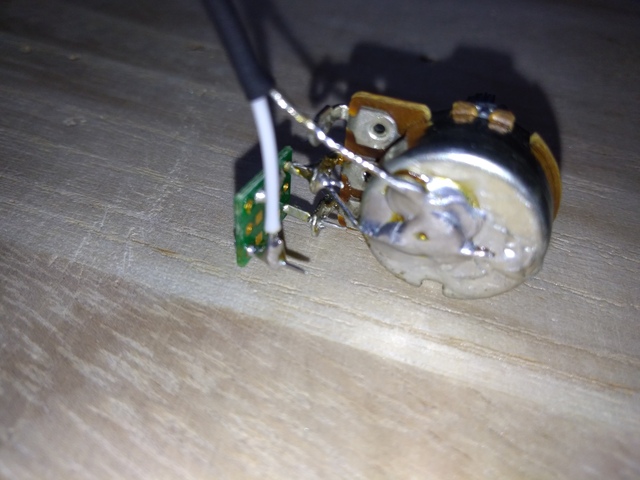
First of all, I made a breakout board for 2SK209-BL, the audio frequency N-channel JFET as I mentioned in Plan of Customizing. I used a lead free solder (Sn 99%, Ag 0.3%, Cu 0.7%) ∅ 1.0mm wire because this breakout board was going to be attached to a potentiometer (POT) through soldering and the solder for the chip would be melted. By using a lead solder (Sn 60%, Pb 40%) ∅ 0.8mm wire to connect between the breakout board and a POT, I can utilize the difference of melting temperature between a lead and a lead free not to melting the breakout board.
* 2SK209-BL is made by TOSHIBA. I searched its obtainability in the world, and the chip seems to be stocked in Asia. Whereas, BF256B is easy to obtain in North America. In this customize, I used 2SK209-BL with SOT-23 package because of its size. However, BF256B with TO-92 package may give us easy assembling rather than SOT-23 one. Although, we need to consider of mechanical vibrations on parts if you install these to musical instruments. You may wonder of why the VHF/UHF amplifier, BF256B, can be act as an audio frequency amplifier. JFET has few materials like diodes. Manufactures may test a chip in several ways, low frequencies or high frequencies; and put different names to a chip for applications, audio or radio. Updated on 11/18/2020: In my experience on making a compressor, BF256B doesn't seem to invert the phase. Whereas, 2SK209-BL inverts the phase.
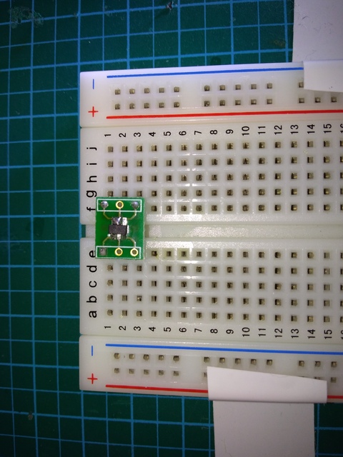
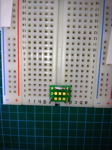
I intentionally connected the pattern for Gate and its neighbor. On the flip side, I connect the pattern for Drain and the another side. Apparently, the solder wettability of the lead free is not better than the lead, so I needed to use metal bridges (the rest of lead frames on cutting) for connecting patterns on the flip.
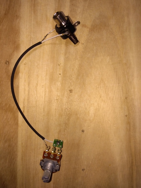

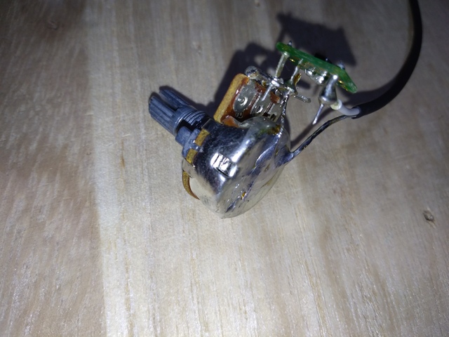
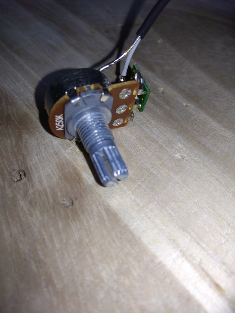
Connected the breakout board and a POT, 250K ohms A (logarithmic) curve which is for controlling tone of the original Les Pauls SL. Therefore, I didn't need to purchase any POT. The wire for connection between the POT and a jack is a thin shielded cable. Note that the jack is Marushin MJ-160M. This jack may help me on Ginza sound. The wiring on the POT should be vertical with sloping, but not be horizontal as I soldered because of the space of the cavity of Les Paul SL. The cavity is 30mm depth, whereas the height of the POT and the breakout board in the cavity is 15mm to 20mm. There is the space to wire vertically. However, the cavity near the POT to control volume is narrow and small space to wire horizontally. Anyway, in this case, this wiring can be cased. Note that I only soldered the center pad of the POT and the lead frame for Drain. Another pad and the lead frame for Source is not soldered for the further process.
I installed these parts to the pickguard. I dummied an original 250K ohms B curve POT used to control volume and changed the place. I wired the POT and the toggle switch. It's a little difficult because the wire placed between the bottom edge of the breakout board and the pickguard. The inner or shield wire is connected to each lead frames of the breakout board connected to POT. Double check not to short the circuit anyway. Make sure to connect the toggle switch to the POT before placing to the pickguard because the plastic pickguard may be melted by heat of your soldering iron. I could remove the toggle switch from the pickguard, and wire this with a POT in the same time to connect between the POT and the breakout board before soldering. However, I also needed to remove pickups if I remove the toggle switch from the pickguard. To hide regeneration of noise by contacting the wire from pickups and the wire to the output jack, I considered of wiring with layering in height.
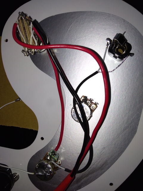
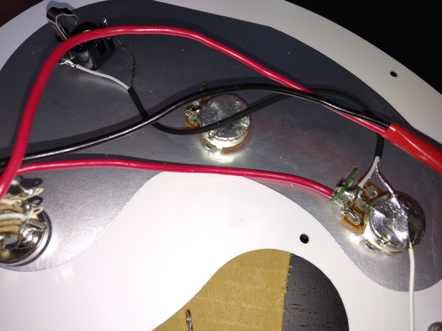

By the way, you can watch there is no wire to ground string. I eventually cut the wire. Working something on the body of my guitar hurts the body, and soldering the grounding wire several time breaks the wire.
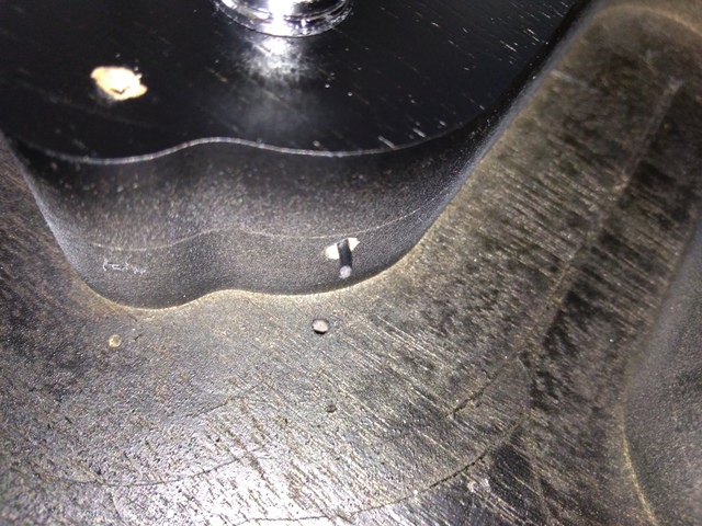
I had a strategy that the white wire can be attached to a set screw on the bridge. I applied Nichifu R1.25-3 non-isulated, a terminal ring, to connect the set screw and the wire. Note that set screws of Epiphone Les Paul SL seem to be M3 ISO/JIS screws. Whereas pole pieces seem to be M8 ISO/JIS screws. As for tapping screws, I found that these seem to be 2.5mm * 9mm ISO/JIS, but also special. I'll report about tapping screws in another story. Screws made with inch are difficult to obtain in home improvement retailers in Japan. If you maintain guitars in Japan, using screws made with millimeter is better than using inch ones.
Updated on 7/28/2021: To make the wire for grounding, its length should be 150mm. You adjust the length of the wire after setting the pickguard and the bridge on the body of the guitar. Note that set screws for octave tuning of the bridge on Les Paul SL is similar to set screws for adjusting heights of strings on several bridges for ST style guitars as long as these are sized as M3 and have 10mm length.
* So, guitars made in Asia typically use ISO/JIS screws. In past days, Asian factories of Guitar manufactures in the U.S. sited in Japan. I don't know how Japanese business owners and politicians gave away the right to the other Asian countries, but the action of them apparently affected the economy in Japan. Riches could buy estates, stay in gracious housing areas, and enjoy on beach sides, but they are a little part in the country. Almost part in the country doesn't have enough jobs at last. SO, HOW DOES THEY TREAT THIS MATTER ON LATE POLITICALLY ELECTORAL OCTOBER "20-20 NATIVE AMERICAN" RIGHT NOW?
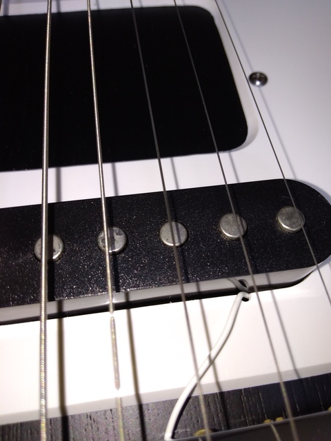

I drilled the pickguard on a side of bridge pickup by 2mm pin vice and a diamond coated needle file which is small. The terminal ring is crimped to connect the wire, but I also soldered by a lead free.
After customizing, I now get the electric sound well. I only need to control the TONE knob on the place where the VOLUME knob was placed. By this customizing, volume controlling stays handy. On dialing 3-4, a low-pass filter of a pickup coil effect the sound. On dialing 10, the sound becomes trebly. The volume is controlled by heights of pickups and the knobs of my DIY preamp. In the future, I may need to obtain a volume pedal on the output of the preamp.
I concerned about mechanical vibrations from the breakout board on playing and it would sound acoustic resonance. So far, it doesn't occur. However, I need aging test of parts including the shielded cable I applied.