RasPi 8: Guitar Pedal Effected by Raspberry Pi Pico (Frequently Anticipated Questions)
Last Updated on July 20, 2023
First Published on October 12, 2021
I listed up anticipated questions and answers from users, builders, and enthusiasts.
-------------------------------------------------------------------
Q1-1: How to install software to Raspberry Pi Pico (referred to as Pico) on the board?
A1-1: Detach your Pico from the board and install the software using a USB2.0 cable. You can also use small IC clips to connect with another Pico which is installed Picoprobe. For more detail, visit raspberrypi.com, and obtain a downloadable document, "Getting started with Raspberry Pi Pico".
Installation of Software Using IC clips: Take care of accidental releasing IC clips from pads.
Q1-2: Any binary files?
A1-2: Binary files tends to cause troubles on its installation. Pico has two methods to install software and each method need a unique file for installation. Fortunately, Pico and this guitar pedal are open-source and open-document. You can make binary files with several steps.
Q1-3: Is the DC Jack is center negative?
A1-3: Yes. my AC-DC power supply adapter is rated on 9V and 500mA with a center negative ⌀2.1mm internal plug.
Q1-4: What about its input impedance?
A1-4: It's 500K ohms according to an AC equivalent circuit in small signal analysis. When you switches off this pedal, 500K ohms resistance has been still set in parallel with receiver's input impedance. Therefore, the reduction of the combined input impedance at a receiver would be approx. 67% loss (1M ohms becomes 333.3K ohms) if you directly connected a guitar with this pedal. When you use a guitar with a high power pickup and a 500K ohms POT for controlling its volume, high volume may be suppressed by receiver's combined input impedance at 333.3K ohms. If you use a buffer with a 100K ohms resistor to the ground on its output before this pedal, the reduction of the combined input impedance at a receiver would be approx. 16% loss (91K ohms becomes 76.9K ohms). If you use another buffer with a 10K ohms resistor to the ground on its output before this pedal, the reduction of the combined input impedance at a receiver would be approx. 2% loss (9.9K ohms becomes 9.7 ohms). In these cases with any buffer, the output impedance of a buffer would be approx. 1K ohms and its high volume is kept. I assume that the unique input impedance of a receiver is 1M ohms to calculate loss ratios. If you connect two clones of this pedal in series, the loss ratio increases.
* You can observe that the input impedance of an Op Amp to control Gain in an overdrive pedal is typically low by a parallel terminating resistor. The input impedance can be low because a buffer before the Gain stage has been already received the input signal. The Gain stage also amplifies unintended noise, and an overdrive pedal needs much amplification. Therefore, the low input impedance helps to reduce unintended noise amplified at the output. A buffer before the Gain stage typically applies a bipolar junction transistor (BJT) with a common collector circuit that the input impedance can become high in spite of low resistance between the emitter and the ground. This system would help to reduce unintended noise derived from a high value resistor.
* The true-bypass, that grounds circuit's input during switching off and cuts 500K ohms resistance in parallel with receiver's input impedance, may make popping noise at turning on and off. The popping noise on true-bypass would be derived from switching surge, and it should be avoided to protect components in a circuit. I also thought buffering by Pico on switching off, but these pedals are digital although the sound is not wrong. In case, I added a switch to change from any effect to a buffer, and vice versa.
Q1-5: What about its output impedance?
A1-5: The output impedance (ZO) is just internal resistance of LM358. In datasheet, it seems to be approx. 50 ohms on sourcing (open-loop ZO), and approx. 100 ohms on sinking (closed-loop ZO). However, these are tested with direct current, and the ZO seems to become low with alternating current. The ZO is derived from transistor's collector-emitter resistance in the Op Amp, LM358. The 1K ohms POT internally inputs the signal from LM358 as a parallel terminating resistor which affects the input impedance of a receiver. This is because of controlling the output level, but not enhancing efficiency of electric power. In my experience, popular products have fixed 10K ohms or 100K ohms on these output, and these are following a manner as audio equipment to match receiver's input impedance. I think the manner is derived from radio equipment which needs to consider cable's impedance. In the audio world, cable's impedance is considered as 0 as long as the output impedance is enough low to hide inductive reactance. Although the parallel terminating resistor should be applied close to an input in the radio world because of cable's impedance, I applied this close to the output of this pedal. Therefore, the input of a receiver will probe the voltage from the output of this pedal including a cable connecting the receiver and this pedal, and occurred voltage on a cable will be abandoned. Note that the resistor also prevents overflowing electric current on an output jack in case. 10K ohms one or 100K ohms one is said to be the certificate for an appropriate product.
Q1-6: There is no 16mm 1K ohms B curve 1/8 watt POT with a knurled a shaft and solder lugs in any store. What about an alternative of this?
A1-6: You can also use a 16mm 10K ohms B curve 1/8 watt (125 milliwatt) one. If you think of the difference between sourcing ZO and sinking ZO of LM358 as I mentioned in A1-5, 10K ohms one would be better than 1K ohms one. If you think 10K ohms one is high and noisy, you might use a 16mm 10K ohms audio (A curve) one. However, POTs for audio are probably rated 60 milliwatt, but I guess the rate is the average power from the alternative current. In this pedal, LM358 outputs up to 6Vp-p, although VCC of LM358 is 9V and -1.5V to calculate its maximum range. In this situation, the power from LM358 would fit within the half of the rate of each POT. I think that any additional resistor with the 1K ohms POT because of this calculation.
Q1-7: Can I connect headphones to the output jack?
A1-7: NEVER DO IT. IT'S SO DANGEROUS. OTHERWISE, THIS PEDAL STARTS SMOKING! I don't apply any damping resistor in series with a 1K ohms POT (RV1 in the schematic Rev. 1.52 of the previous post) for controlling output level. If you place a damper, 390 ohms 1/2 watt one is needed with a 1K ohms POT. If you want to keep under Op Amp's absolute maximum rating on power consumption in case of connecting a pair of headphones or a speaker, a damping resistor is needed, and a 10K ohms POT and a 390 ohms damper (e.g., between the 1 pin of RV1 and the T_2 pin of J4 in the schematic Rev. 1.52) become the selection to structure the unit to control the output level. On the usage of this pedal, smoking possibly occurs when you turn to the quarter around the maximum level when you connect headphones or a speaker to the output jack. I think speaker amps also smoke when you connect a 0 ohms resistor to make a loop although it would trigger a fuse blow. Further discussion should be held on the product underwriting. I imagine the situation of making a short circuit on the output when this pedal is powered on to play a guitar. Besides, I also think of Op Amp's behavior on outputting high current with its output impedance that is made of inner transistors. Note that the long runner LM386 connects to a speaker through a capacitor without a dumping resistor in its regular usage. However, its absolute maximum rating (power dissipation) is around 1 watt, having noticeable output impedance. The modern logic of underwriters may suggest to add a damper when I consider the supplying environment of LM386 these days.
* The calculation as described above is assuming direct current. Alternating current would be use average power or efficient power to show its power consumption. If you consider efficient power of alternating current, the damper would be 200 ohms. However, we need to think of the tolerance of the power supply, and I think of +20% tolerance to the 9V DC power. I use 240 ohms one in my DIY preamp. However, the length of a 1/2 watt axial lead carbon film resistor is 6.3mm at minimum (KOA CFS1/2), and the length of a 1/4 watt one is 3.2mm at minimum (KOA CFS1/4). You may prefer to use a 470 ohms 1/4 one with a 10K ohms B curve POT (I don't think that it's a golden rule though).
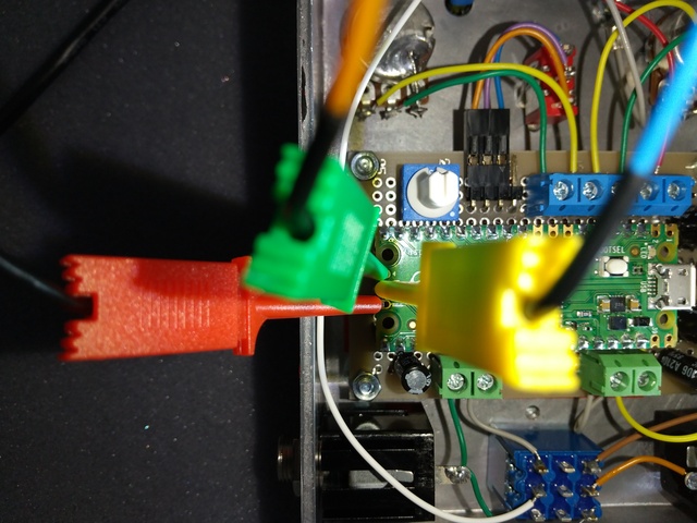
Replacing the orange wire between the push button and the output jack at the bottom right in this picture with a 240 ohms 1/2 watt carbon film resistor helps to resolve this smoky issue in A1-6. I assume that the input impedance of a receiver is 10K ohms at least. If I needed to recall this pedal, I do this work with respecting underwriters. Another method is to add a 240 ohms 1/2 watt (or 470 ohms 1/4 watt) dumping resistor to either edge of the yellow wire between the green screw terminal and the 1K ohms POT (RV1 in the schematic Rev. 1.52) at the center right of this picture. Besides, the 1K ohms POT is needed to be replaced with a 10K ohms POT. I think presoldering a 6.3mm/3.2mm length resistor to the yellow wire with covering with shrinking tube for insulating, and soldering the presoldered resistor to the lug of the POT directly. Take care of a short circuit made of the wire and the lid of the box.
Q1-8: How about its current consumption?
A1-8: In my experience on developing, the current consumption with a 9V battery (actual approx. 8.6V) is approx. 35mA, and I rate this guitar pedal as a 50mA consumer.
Q1-9: What about maximum input voltage and maximum output voltage?
A1-9: The maximum input voltage is at +-1.5V, and the maximum output voltage is at +-1.5V (assuming with a 9V power supply). The input is compressed, amplified, and effected in Pico. Then, the input is clipped at +-0.75V before output from Pico. Before the Op Amp, the output is reduced with approx. Loss 2 (6.02dB) because of the low-pass filter to PWM pulses. On the Op Amp, the output from Pico is amplified with Gain 4 (12.04dB). For example in the Buffer effect with no effect, the input at 0.1875V is amplified to 0.75V in Pico, and becomes to output 1.5V at the full level. Note that the maximum output isn't considered a failure mode that may simply output the voltage of the power supply. After building this pedal, make sure to examine the voltage of the output by a voltmeter.
Q1-10: Where to buy parts?
A1-10: I purchased the aluminum chassis online, and electric parts I selected are also purchased online, but these would be shipped only in Japan. In this suffering year, you couldn't visit Akihabara. However, these electric parts and these compatibles are universally obtainable. I used the smallest radial lead resistors and Schottky diodes which are in small packages, but these can be replaced with ones normally sized. Check out parts lists in major distributors online.
Q1-11: What is your guitar to test this guitar pedal?
A1-11: I tested with BST-1R, a Bacchus' ST style guitar with single coil pickups which have ceramic magnets. I think that single coil pickups tends to be less power than humbuckers, and adjusting with single coil pickups would make a universal design for guitars. Note that strings were a set of Ernie Ball Regular Slinky (10-46), and the neck pickup was low to adjust powers among three pickups.
Q1-12: Why do you open source code and documents of this guitar pedal?
A1-12: In view of education, I'd like to dedicate my DIY work for learners. Besides, these are my notes online not to lose.
Q1-13: It seems to be no reliability of this guitar pedal plot which has only a prototype.
A1-13: I'm just testing reliability, and I'll show several demonstrations. However, I think to hide the upcoming season of Black Friday with the lack of electric parts these days in a chilly atmosphere (written on October 25th, 2021).
* (Updated on 11/08/2021) I've started to demonstrate this pedal with my guitars. I told the "chilly atmosphere", but it's not just the matter of my sense. You can check out how activities of influencers especially for commercialism of mass production have decreased. In an expected hard inflation, manufactures tend to select the way to promote their products. They actually know that "leaders in consumers" is effective, and there is a term called "demonstration effect" in economics. However, it causes speculative purchasing that would triggers to destroy the balance between supply and demand when common consumers are willing to purchase their products. Guitarists are not exception, and you may be aware of "some pop" series. The reason of the atmosphere among PR people online is the reflection of economic booming. In this time, I think the people can try "dry run" of their technologies in promotion.
Q1-14: Why is a selector for effects of pedal_multi inside the box?
A1-14: To use this guitar pedal in a stage, "strange" functions shouldn't be sited on the front console because of considering any mistake on footing. You may concern about screws to detach and attach the lid of the box to select an effect. In the mechanical theory, threaded holes of an aluminum box tends to be broken by steel screws. To hide this trouble on inserting screws, you can turn a screw reversely, and confirm that the starting point of a thread of a screw matches with a thread of a hole by slight falling of a screw. Caution that the torque to turn a screw causes to break a thread of a hole if you need much torque in turning a screw. To hide this accident, take care to turn a screw smoothly with turning reversely as needed.
Q1-15: How can I turn the selector (rotary switch)?
A1-15: I use a 0.19in (5mm) flat tip short screwdriver which can fit with the slot on the knob of the selector.
Q1-16: Oops! No sound after stepping on the stump!
A1-16: Half pressing causes no sound because the stump is a mechanically latching switch. Just step on it well. Improve your skill.
* The argument; whether a mechanical switch can be used in a pedal, or shouldn't, is mainly discussed on the stream of mass products. Many manufactures of mass products applied the method that a momentary switch changes the status of a flip-flop circuit that alternates between the buffer mode and the effect mode. If you prefer to use a mechanically latching switch with your DIY pedal, you should know the existence of the matter from half pressing.
-------------------------------------------------------------------
Q2-1: Noise with my keyboard. Are you serious?
A2-1: Internally adjusted for electric guitars with coil pickups. The table of a normal distribution, "int32_t util_pedal_pico_ex_table_pdf_1[]" in "util_pedal_pico_ex_make_header.py" makes compression to the input. You can replace a function at "Table PDF 1" with commented one for the natural adjustment. However, this would also make noise and unintentional distortion with your keyboard particularly on high volume. If you want more natural sound, set "pdf_height_1 = 1" and increase the value of "pdf_variance_1". Moreover, the input impedance of this guitar pedal is 1M ohms for the signal from a guitar, and this impedance tends to have more noise from power source and ground. If you want a model only for your keyboard, you would decrease values of resistors for biasing input signal to 50K ohms.
Q2-2: Anyway noisy. I expected a synthesizer, but it's not on all the way you are.
A2-2: No, I'm on the way to make my guitar pedal with good culture. In the amplification of output of electric guitars with coil pickups, noise can't be avoided. The signal level of these electric guitars is lower than the signal level of modern audio appliances. To amplify the signal of these guitars, noise tends to be amplified too. However, culture and inventions around electric guitars are born with this characteristic. Even now, the best amp for electric guitars is a tube amp because the amplifying characteristic of the tube fit with the signal from electric guitars. I think the importance of the tube as the best guitar amp is nonlinearity of its amplifying characteristic, i.e., a quadratic (U-shaped) curve. Whereas, a bipolar transistor has a logarithmic curve that tends to amplify low level signal including noise more than high level signal. In this guitar pedal, I internally adjusted the inputted signal as I mentioned in A2-1. The table of PDF has a quadratic curve on amplifying, and I weighted the inputted signal using this table. Making a guitar pedal in a digital term isn't a wasted idea because of a designed amplifying curve with high efficiency.
Q2-3: Hmmm, the noise seems to be big by a ground loop. Is it because of no cutting ground wire between an amp and a guitar?
A2-3: DON'T CUT ANY GROUND WIRE IN YOUR CABLE EVEN IF IT'S FOR SIGNAL. DON'T COMMIT TO THE RISK TO END YOUR LIFE. Cutting any ground wire just causes an electric shock to your body. In case of failure of an amp, power voltage may reach your guitar through your shielded cable. If you connected a ground wire in your cable, you would be safe. If not, the electrical power flows into earth via your body. Two types of grounding exist, high frequencies such as noise and low frequencies such as power. To ground high power, your body becomes just a resistor with 200 ohms in some cases. If you want to cut noises which are affected by neighbor's appliances, use ferrite cores and never cut ground wires to remove only high frequencies and stay the DC flow. You would get an isolator made of transformers. I use a DIY preamp to get DC bias to avoid noisy earth voltage. In signal engineering of analog communication, getting DC bias is the common way for improving signal-to-noise ratio.
Q2-4: Here comes popping noise!
A2-4: I think almost popping noises come from electric guitar's grounding strategy. I experienced palm muting (or palm on a bridge) reduces the number of occurrences of popping noises, but touching strings on a fingering board doesn't reduce popping noises. I think this because of resistance and inductance of strings. Touching strings on a fingering board doesn't mean grounding by human body. I experienced touching a POT makes popping noise after stroking without palm muting. Besides, strings would become coils. Intermittent touching strings on a fingering board also makes alternation between charging and releasing of electric power, causing coil surge. Check out 「ふうふう風力発電」(Puffing Wind Power Generator) which is made of a DC motor. However, this generator is not only made of a DC motor which internally alternates between turning on and off, but also using coil surge that is generated on the external blue and red wires connected with a DC motor.
Q2-5: OK, I got you claim, but the reality is with noisy.
A2-5: I know the reality, but the noise is needed for a reality of playing guitar. In the effect, "Planets", I experienced that the low-pass filter significantly reduced the noise. On the other hand, attacking power of the sound was also reduced. The attacking power of the sound shows reality on picking and strumming. If I apply the low-pass filter regularly, this pedal becomes just an audio manipulator, but not for guitars. I think the reason, RC4558 and its equivalents are still favorite as the best Op Amp for guitarists rather than RC4558's successors, is its reactivity to reproduce the reality of the sound.
Q2-6: Direct connecting between this pedal and an audio interface makes wrong sound. Why?
A2-6: For example, my USB interface, UCA222 inputs up to 2dBV = approx. +-1.2589V. If the input exceeds over 2dBV, the sound becomes clipped. Besides, I plot this pedal without any tone circuit to stay player's intention such as picking. The input from a microphone to get the sound from a speaker tends to have wider range than the direct connecting without any speaker. Several amps input more voltage than my USB interface, and the circuit for equalizing (e.g., bass, mid, treble, etc.) arranges the wave of the sound. Besides, a voice coil in a loudspeaker becomes a low-pass filter, and in-phase and out-phase of the sound from a speaker affects the input of a microphone. In conclusion, I think sound from a speaker is compressed. Try a low-pass filter in you mixer and an editing software if you feel any wrong sound via direct connecting.
Q2-7: Noise on no playing form this guitar pedal with a battery is apparently bigger and more cyclical than the one with an adapter. Why is this mystery?
A2-7: It's depending on the environment of your audio settings. Your grounding strategy affects the condition of the noise. Besides, to monitor noise, you need several minutes after setting all of the system including you. On the other hand, my circuit design is minimum to remove noise from the power and ground. Note that this pedal apply a moving average for biasing, and approx. 30 seconds are needed to stabilize biasing after powering on.
-------------------------------------------------------------------
Q3-1: Digital distortion? Gonna crazy.
A3-1: I know intentionally distorted sound from this guitar pedal is just "fried", and I also think sound of distortion should be thicker, i.e., boosted bass and treble. In view of bass and treble, this sound is not good. The better sound from an analogue amp is made of high voltage with noises from low efficiency. I just honestly suggest this sound as new one, but not such a sound.
Q3-2: Do you know compressor pedals?
A3-2: As guitar pedals, there are several types of compressors. An opto-isolator or an operational transconductance amplifier (OTA) is typically the core of the circuit. An opto compressor uses opto-isolator's nonlinearity for compression, and an OTA compressor acts like an automatic gain controller (AGC) of a radio receiver. I've made a plot of an opto compressor, and I've confirmed the sound is nicely fat. Meanwhile, this pedal compresses inputted sound as I mentioned in A2-1. Several compressors have "Attack (time to reach intended compression rate)" and "Release (time to recover from compression)" knobs. These are envelope generators limited to signal surpassed a threshold on "Attack" and signal fell below a threshold on "Release", and the threshold would be measured by root mean square (RMS) with compressing delayed sound to resolve phase shift of RMS. I think the latency on the compressor with RMS may become an issue on your live and/or online stage performance. I introduce the Envelope effect which can change the "Decay (after threshold on attacking)" and "Release (from decaying)" time. Both Attack/Release compressors and my Decay/Release Envelope effect make a trapezoid envelope to reduce sound. However, Decay/Release has the same time. Decay/Release makes an envelope forming an isosceles triangle, which is triggered by the threshold on attacking of the input from a guitar. The bottom of sound loss on the Decay/Release envelope is limited by effect's configuration, resulting in making a trapezoid envelope.
-------------------------------------------------------------------
Q4-1: Pico can't make any guitar pedal because of low-spec.
A4-1: I think your opinion is "yes" if you make a high-end pedal. I made this pedal with Pico mainly for live performances although I recorded several guitar plays with direct connecting between this pedal and an audio intarface. The ability for floating point arithmetic isn't fit with real-time data processing, and accessing SRAM needs a time to spend clocks. However, fixed point arithmetic gives Pico enough speed, and considering a limited number of accessing SRAM saves low latency.
Q4-2: What about Pico's durability?
A4-2: In my developing, no Pico has been broken. In some cases, installation of software can't be done (via USB and SWD), but I guess it occurred because of unintended electric charge on my developing board or Pico. This issue resolved after a while.
Q4-3: Hey, a 9V jack connects to your chassis. THIS IS JUST YOUR TOY.
A4-3: The short answer is "yes", but the long answer is "THIS IS NOT YOUR HOBBY". Probably, you mean RC4558 and its derivations which are dual power Op Amps. I know RC4558 is a well-known Op Amp for audio amps, and a lot of enthusiasts used to want small noise Op Amps like RC4558 and its modified ones. Considering the amount of sales, engineers should select RC4558 variants. Whereas, I apply LM358, a single power Op Amps to hide complexity in the electric circuit. I couldn't make my prototype board without LM358 in view of small amount of parts to fit with the tiny "C" board. Another Op Amp with single power is LM386 which is popular on the current DIY world. In the same time, New Japan Radio (founded by Japan Radio and invested by Raytheon) has deprecated a version of LM386 by National Semiconductor (now in Texas Instruments), and left a version of RC4558 by Raytheon (now from Texas). Even though LM386 is not for general purposes, but only for audio, this story tells how RC4558 variants have dedicated for audio systems commercially. Even in the circumstances, I can say LM358 will be used in the future because it has good output on low voltage close to GND. Note that you may see the occurrence of phase reversal if you replace LM358 with RC4558 in the board I plot. Note that RC4558 variants fit with a BTL (bridge-tied load) that is popular in car audio. However, output impedance of RC4558 variants isn't low enough to drive a speaker. To drive a speaker, you need to add a pair of audio power transistors on the output of RC4558 variants. Although there are several combined components, RC4558 variants are keeping its popularity.
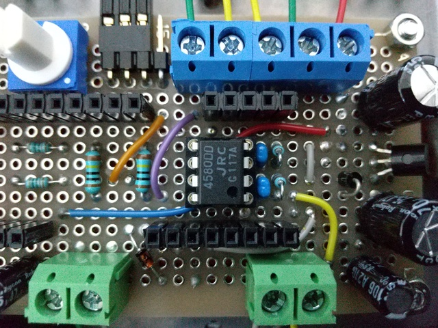
I confirmed the one of RC4558 variants doesn't work on my prototype board which is needed a single power Op Amp. Note that replacing an Op Amp is a difficult task because of the height of sockets for Pico. DIP IC extractors wouldn't be inserted to the underneath of the Op Amp. This NJM4580DD will be used for another audio project that I'm currently planning to know ideal virtual grounding for RC4558 variants.
Q4-4: What is Op Amp?
A4-4: Op Amp is an abbreviation of an operational amplifier which is an integrated circuit of a differential amplifier and other circuits to stabilize as a linear amplifier. Op Amps are used in audio equipment like synthesizers, industrial measurements for phenomena, and so on. Its unique function of linear amplification is invented to be used as a computer in W.W.2. Whereas, tubes and transistors don't have the function of Op Amp. Many combinations of tubes and transistors for amplification tend to be exponential, but the combination as an Op Amp realizes an ideal amplification "in some range". Op Amp is used as an adder, a subtractor, an integrator, or a differentiator like a slide rule. Today, Op Amp is also used as a buffer on a PWM output from a digital chip, and on an input to an ADC.
Q4-5: Op Amp smokes!
A4-5: It's wrong wiring! Power-off anyway! I experienced my universal board underneath a heated Op Amp was melted (with no smoke!).
Q4-6: Why do you use a technique of a difference amplifier on your circuit design?
A4-6: The technique of a difference amplifier cancels common-mode noise typically from a digital circuit. If an amplifier on the output stage can't cancel noise, resonance would occur. Fortunately, an output from PWM can easily invert another output, even it can change voltage bias to fit with the working range of an Op Amp such as single power one. Note that wire lengths of positive and negative outputs from the RP2040 chip to the Op Amp should be the same to reduce conductive noise (especially for high frequencies). In my circuit design, I tried to adjust each wire length to be the same, but I didn't consider the thickness of the board.
* In Q4-4 and A4-4, I noted about "differential amplifier" that is a circuit to be used in an Op Amp. The "difference amplifier" is a technique to use an Op Amp.
Q4-7: Laminated caps which is mechanically noisy? Don't take a technically funny joke.
A4-7: There is a theory that laminated ceramic capacitors become a piezoelectric element which makes voltage by a mechanical impact. In audio equipment, film capacitors are preferred rather than laminated ceramic capacitors. However, I use these for 0.001 microfarads and the power to make voltage would be lower than the one in a guitar. Note that a typical film capacitor in a guitar is scored at 473 (0.047 microfarads).
Q4-8: I checked your preamp and its usage of JFET is apparently strange. Why you don't have any biasing like self-biasing for JFET not to touch positive gate-source voltage that is dangerous. I know amps use self-biasing for JFETs and tubes, and you doesn't. START FROM A TRASH PICKER.
A4-8: In my experience, a company that its recruiting post to join is only a trash picker doesn't need any idea by a human. Furthermore, some company is justifying this bad habit. A grid leak of a tube occurs on positive grid voltage, making further grid leaks. Whereas, JFET doesn't have a leak like a tube. Gate to Source of JFET is just a diode. If the gate-source voltage surpasses around 0.6 volts, the current flow occurs, but it's reversal of a leak of a tube. I don't say JFET doesn't need biasing, but I don't need it in my preamp with the small signal under 0.6 volts from a guitar.
Q4-9: Why not MIDI synth?
A4-9: The word "MIDI" doesn't describe its variants. Now MIDI on newcomers are with a USB (2.0) jack, but original MIDI is a pair of IN and OUT serial jacks. Any MIDI jack would be nothing because of Bluetooth. In making a MIDI synth, the USB connection would be difficult in view of handling noise, and the serial connection would be old in view of suitable electric parts, typically a logic IC SN74LS14 for OUT, and a high-speed photocoupler 6N318 for IN. Keyboard musicians may handle changes of MIDI interfaces since decades ago, but as a hobbyist, it's not fun. The signal of a guitar is analogue and having noise, but is also receivable by a lot of methods with various parts. Note that I made an experimental MIDI synthesizer with Raspberry Pi Zero, 2B and 3B. So, you would also request a music box, and I would make a music box with Pico. I have already made a music box by ATtiny. ATtiny consumes less electric current than Pico. I think the demand of a music box is in the field where chips are required to be reliably robust. Note that my oldest Pico isn't broken even it has passed through the development of this guitar pedal.
Q4-10: Wireless is just popular, and there are XLR output and USB interfaces in recent gadgets.
A4-10: Sorry for no wireless. A XLR output may be a good idea. A USB interface is not great. I expect the lawsuit among big audio companies will become about technologies of USB interfaces and wireless connections with personal computers, smartphones, and tablets. In addition to Serial Wire Debug (SWD), you can use a USB cable to install software to run Pico for this guitar pedal, but this guitar pedal can't receive any command from personal computers, smartphones, tablets, and similar appliances to change parameters for effecting audio signal. Although there are communications between Pico and computers when installing software, these communications aren't intended to change status of any function in a working audio equipment. Big companies may not set a lawsuit against an individual. However, if they do so, I'll counter by claiming compensation for personal suffering causing from a logically invalid theory and sending my letter to "fair" tech Media.
Q4-11: You don't use XIP. Do you really want to dedicate something to our electronics?
A4-11: XIP communicates with an external flash storage. This communication makes digital noise. I made pedal_looper in addition to pedal_multi, but it has digital noise on its output. I guess this noise comes from the communication between RP2040 and the external flash storage. If you want more detail about XIP, check out a chapter of my opinion in my project.
-------------------------------------------------------------------
Q5-1: Would you sell this guitar pedal?
A5-1: I wouldn't sell this guitar pedal. In my student era, pedals are lined up in shops at 5000-15000 yens (around 50-150 dollars). I thought I couldn't purchase pedals. Young guitarists in Japan thought purchasing pedals was just a good investment for their professional future. They could also think it was a trial of commercialism. In fact, there could be a business between guitarists and sellers, but I can't prove the scene in the past. Whatever, I didn't understand this idea at that time. I now get a pedal by my DIY work with several investments I can understand.
* Since now, I expect that the guitar scene would be boomed among people, mixing venues and online. For decades ago, the scene used to be compete with electric music like Hip-hop, Eurodance, House, etc. I worried about the ruin of the scene, but several news in this time report the good amount of sales of guitars (many writers point out acoustic guitars though). Music business has a mystery in view of marketing, because factors to make booming are so many. These keys are not only from consumers, well-known "teens", but also from the need of miscellaneous "outfielders" because every music has aspects of education, therapy, and business. I also heard a rumor that Californian Fender will use "steamed (I hope so)" pine woods for bodies of its guitars, and I like the expected dry sound from Telecasters which was made a prototype by a pine wood. This rumor tells that we should know music is also an environmental business. I think young people will be involved in the business like influencers these days. My two advises to young people are "almost all deals will be just fakes in your future", and "let's meet on the street and cheers if you are enough to be eligible."
* Note that roasted pine has been already in the regular lines of Fender as models of American Professional II since 2020. It's in substitution for ash which suffered from climate change in North America. Pine woods need heat treatment, roasted or steamed, and drying not to ooze resin. California apparently need to maintain its forest of pine trees in view of its disaster defense. As a local entity, it's an honest way to use the sustainable timber. The topic among guitarists would be the usage of pine in substitution of alder. Guitars with pine bodies tend to have big acoustic sound, and guitarists think its characteristic is bright. In modern music, the bright sound from a guitar is preferred because of combinations with other instruments. In view of mixing, high tones don't need high power to hear well. The usage of pine may have to become popular in this music scene in my opinion.
Q5-2: What is the name of this guitar pedal?
A5-2: It's just "Kenta Ishii's Guitar Pedal". It hasn't become a product yet, and it doesn't have a trademark. Therefore I'll create a name as a trademark for this pedal, if this pedal is introduced as any product such as a PCB or a DIY kit. You can search "PICO" in Trademark Electronic Search System (TESS) in United States Patent and Trademark Office, and you can find out the word is widely used in many trademarks (you would also search trade marks at GOV.UK). Note that "PICO" means a peak and a summit in Portuguese ("PICCO" in Spanish). When I name this pedal, I won't include the word "PICO" because of the digital term that wouldn't fit with common perceptions people could have for this guitar pedal. I'm using "pedal_pico" only for the project name with KiCad to design the hardware prototype. Distinguishing between a product (or service) name and a project (or code) name is generally recognized such as the code name to the project of developing iPhone, "Purple".
* Several combinations of the word, "PEDAL", and other words for a trademark of a musical instrument to effect sound from electric guitars are registered because "PEDAL", expressing to step on a button using a toe, has been known as the term to call the musical instrument on trading. "PEDAL" has been often used as brand names and company names to manufacture and sell the musical instrument. As a trademark of the musical instrument, "PEDAL" is not identifiable. "PICO" is a word meaning very small in English language, and it's not a coined word. Whereas, "PI" is a word meaning a Greek letter in English language, and it also means the ratio of the circumference of a circle in mathematics. Caution that "RASPBERRY PICO" and "RASPBERRY PI" would be recognized as a similar trademark because the word "RASPBERRY" has been known as the term to identify a brand name and a company name to manufacture and sell single board computers (and also servicing computer education). Besides, "RASPBERRY" and "PI" are separable to identify the brand name and the company on trading these products and educational services (e.g., the company uses the trademark illustration designing a raspberry). In contrast, I think "COMPUTER PICO" and "COMPUTER PI" would be not a similar trademark because "COMPUTER" means a machine to be traded and it's not identifiable.
* Anyway, senses of digital terms should be avoided to sell guitar pedals. "PICO (an alternative to PIKO = ピコ)" is also a mimic word to show sound of retro games in Japanese language. In a delay circuit for guitar pedals, the digital chip, PT2399, is almost only one to be accepted by a half of guitarists, and there is MN3005 or MN3205 for an analog delay which can be widely accepted (I think that MN3005/MN3205 is a series of latch logic that can store an analog value, and it needs digital clocks generated by another IC). Therefore, commercial builders think the luck of obtaining MN3005/MN3205 for an amount of sales, but not the luck of a unique circuit design. Guitarists are just sound creators to select reliable gadgets, but not performing inventors. If I sell some lot of my "PICO-SOME" guitar pedals as any form of a product in the near future, I'll face the reality that guitarists will recognize my pedal as "Pedal non grata". Especially, guitarists tend to dislike software effects on computers because they use acoustic feedback between a speaker and a guitar in rock music, and this feedback means a glitch that may affect digital gadgets. This pedal is just stepping on the phase to demonstrate by myself right now. If you have any opinion and question about this pedal, don't hesitate to contact me.
Q5-3: No need of buzzin' questions as above at'll.
A5-3: OK, I'm just buzzed about questions to hide buzzin' online.